Finally, I did it! I found a computer from the 1980s – two of them!
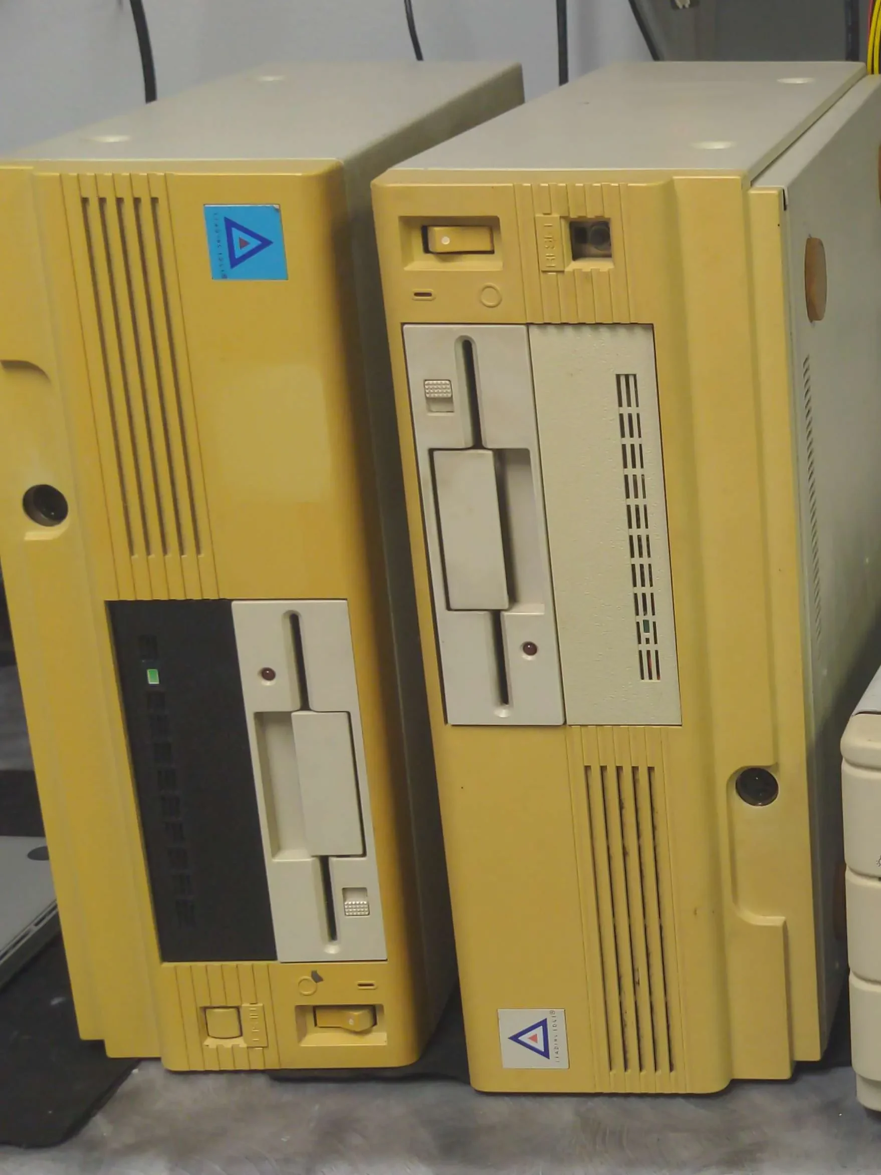
On March 3rd of 2024, I found a trio of oldies, two of them being identical units – the Leading Edge Model D (DC-2011), made in 1986. All my other units have been from 1993 at the oldest! The front bezel plastic is severely yellowed, and the reset button is missing on one, but otherwise I would say they are in good condition for their age.
Testing
They sat in storage for a long time, since I have too many projects for a busy life. But in August of 2025, I decided to finally take a look at them! First I took a peek at the insides to make sure nothing weird was going on. I checked the CMOS batteries, and though it’s of the type known to leak, thankfully it had only made a small mess that didn’t harm any circuit board traces. Good. All else look normal in here.
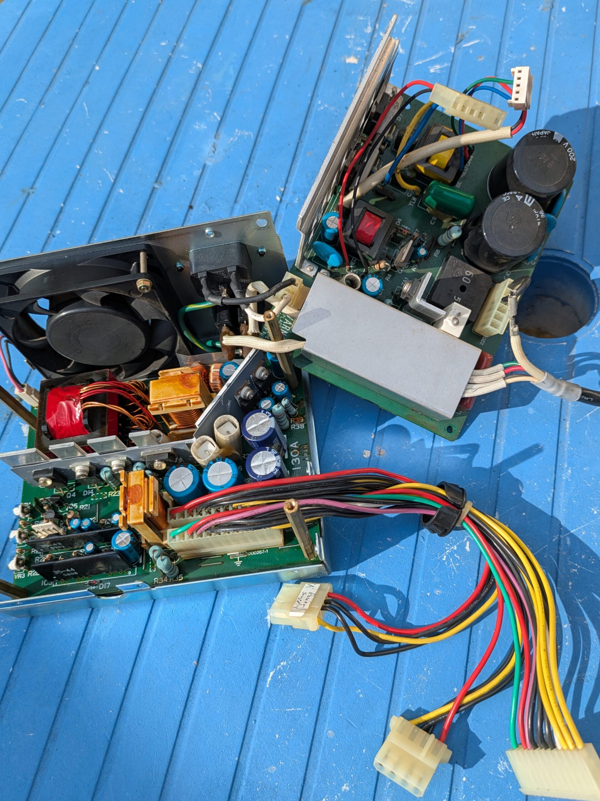
After that, I decided to check with The Retro Web’s Discord server to get input on the power supplies in these things, to make sure they’re not of the type that’ll explode when I turn them on! I’m usually shy on Discord, but I’d rather reach out than blow stuff up! I know some units of this vintage can be prone to that. The power supplies are both of this model: DC-Pack NK-130A by Daewoo. In fact, the motherboard is also made by Daewoo. Perhaps that’s what the Model ‘D’ indicates.
Thankfully, it sounds like these units aren’t evil bombs, so I went ahead and gave them a try!
And… they don’t turn on. I guess that’s not terribly surprising. I get an inrush current from the PSU, but nothing happens when I flick the power switch. Nothing looked amiss on the inside of the PSU, at least.
So, the question comes up – is this a power supply problem, or a motherboard problem? To answer that would require another power supply, and thankfully I do have more old power supplies. But they’re of standard AT type, with the P8/P9 connectors. This one has just one big 12-pin connector, so it’s not gonna work!
Or, will it? I decided to do some searching, and I came across this forum post, where the poster says standard AT PSUs are pin-compatible! Sure enough, I investigate and compare the connectors, and where each wire color changes is the same positions across both, implying that they’re of compatible pinout.
So, I decided I’d hook up my known-good Astec 145W AT PSU to this thing, and hope for the best. I click the power switch, and… the same thing happened! May or may not be conclusive, considering it’s not an exact match, but if it’s truly pin-compatible then that’d mean this is a board issue. For now, I’ll assume that it’s an exact equivalent.
Short Circuit
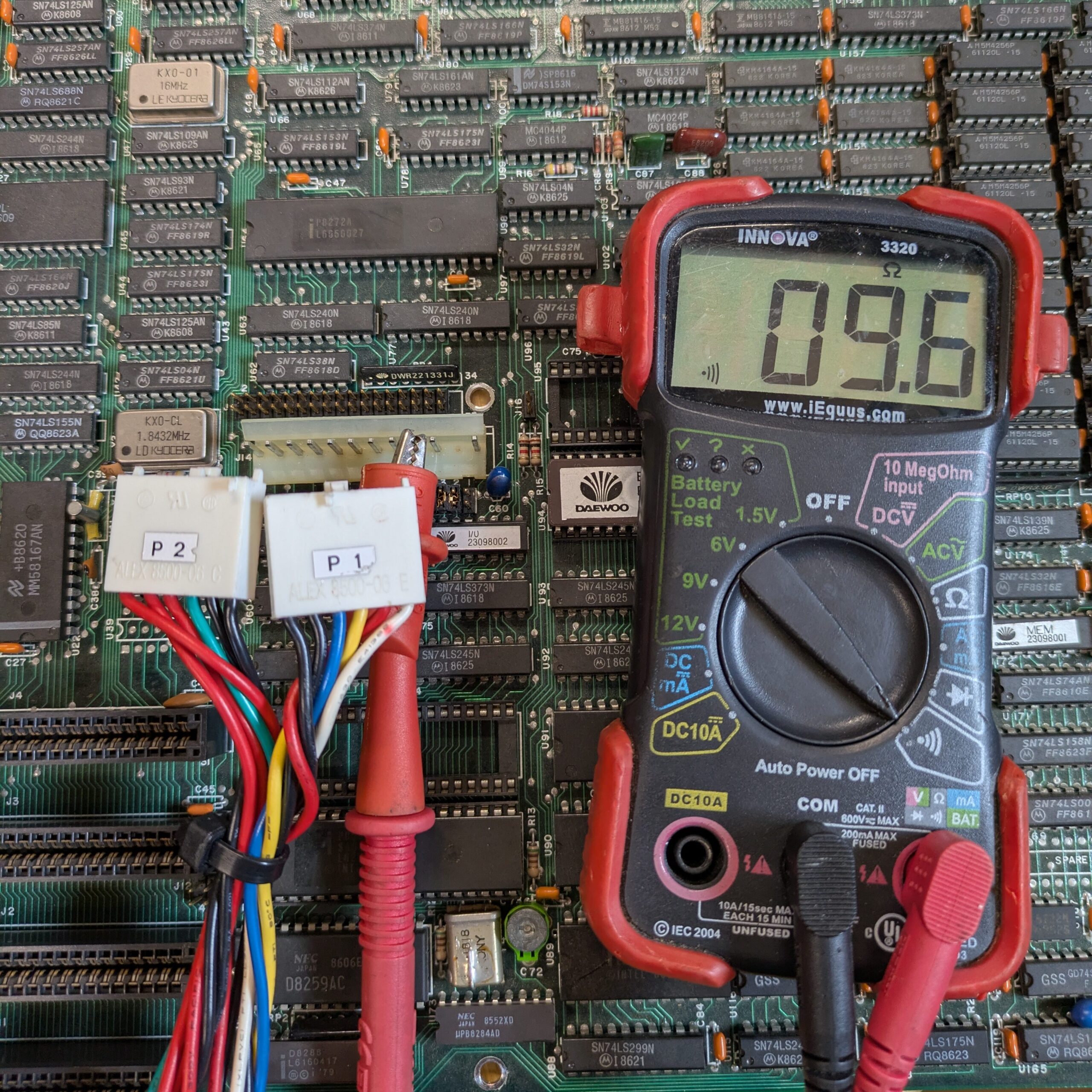
I broke out my multimeter, and I found the problem – an entire power rail is shorted to ground! With one meter probe hooked to the board’s metal grounding area and another onto the +12V pin of the motherboard, I get a reading of a bit shy of 10 ohms! None of the other voltage rails are that way, so that definitely seems like an issue. (And on the other one, the +5V rail is shorted instead!)
I investigate more into this, and found another forum post pertaining to the IBM 5150, which like this computer, features blue tantalum capacitors on the motherboard, which are prone to shorting out. There’s ones right near the power connector – that’s probably it, no?
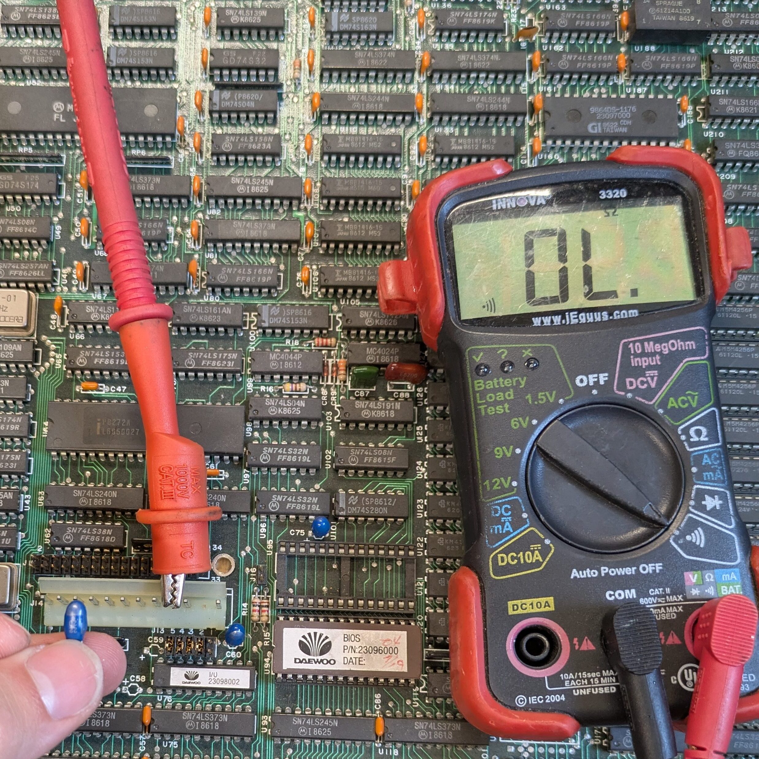
And bingo!! With one of those removed, no more short! So, clearly that’s the problem, and I’ll need to swap out all those tantalums. There’s nine 22uF 20V tantalums, and one 47uF 20V. For replacements, I could only locate up to 15V, and seeing as the highest voltage of a motherboard is 12V, I went with that. Now, I await the capacitors…
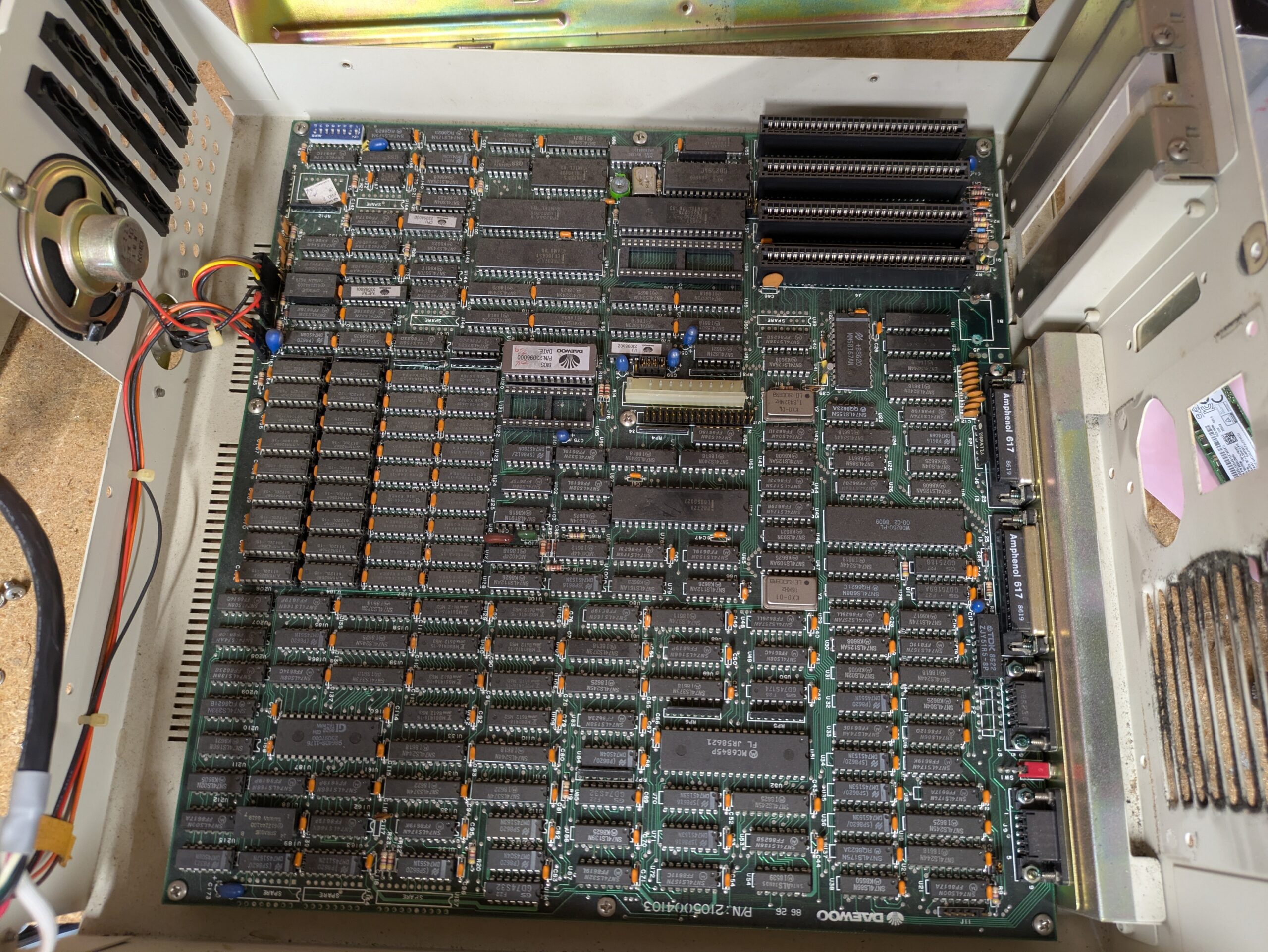
But in the meantime, look how beautiful the motherboard is! This is a work of art right here – if I got a board like this for scrap, I’d mount it up on my wall!
Tantalums!
On August 16th, I received all of my tantalum capacitors for the two! Since the first unit at least seems to have a working power supply, I’m fixing it first, and I’ll deal with the other one later. And with some soldering later… behold!
It powers on – and with such roaring sounds from that hard drive! Unfortunately, with a lack of beep codes, I don’t know if it’s working or not. I fear that without a proper 9-pin CGA monitor (or conversion), I may not be able to determine that. But it’s not over yet! I might be able to pop an ISA VGA card in here, or maybe there’s some other hack I could do. To be continued!
Getting video output
With the continued help of The Retro Web’s Discord server, I was referred to this page with IBM 5150 jumper settings. Turns out, as one of many IBM PC clones, this system shares setting configuration, and it’s thru this way we can tell it to display thru an ISA VGA card.
By flipping SW1:5-6 both from OFF to ON, the board will use an external ROM – in other words, our VGA card. I used an AcuMOS AVGA1, which is a rebrand of the Cirrus CL-GD5401.
And… behold!!!
The Plot Twist
Wow! So I’ve got this thing displaying. Now what? Well, as it turns out, there’s more problems! After a very short time, the whole system locks up, and pushing the reset button yields no more video signal. It’ll refuse to work at all from this point forward, until it’s sat for about an hour or two. Attempting another power-on will result in the same – it boots, but then locks up, so on so fourth.
Great, is that some capacitor problem, whether of one I installed, or some other? This would happen with either power supply I use, whether an original Daewoo part, or my Astec AT supply I use as a tester (which came from a Gateway 2000 4DX2-66 that died a long time ago).
Beginning to be frustrated, I turn once more to the Discord server that’s been of such help thus far. One smart member who deals with arcade machines informed me:
Don’t waste your time with the capacitors, don’t worry about them. That’s definitely a RAM issue. There’s a chip with a fault that, once it heats up, it stops working. You can use freeze spray to determine which one is the culprit.
Fascinating! I hadn’t dealt with anything quite like this before. But indeed, of the several boots I had tried, several would throw memory parity errors. Below is one such that spoke the most of it.
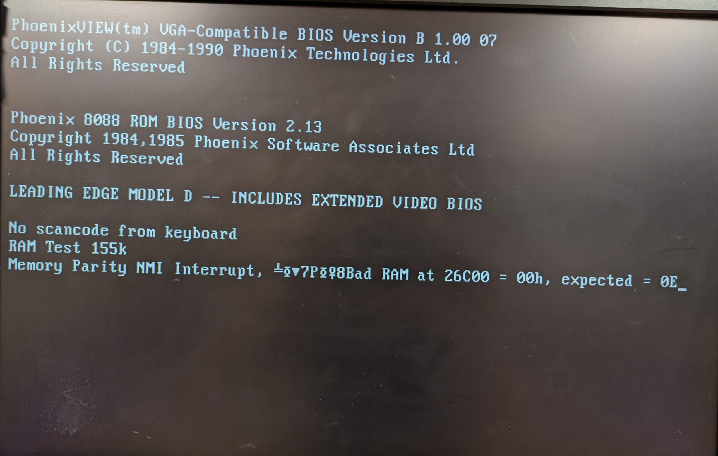
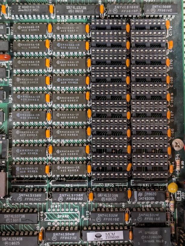
Now, the tricky part is this – one would normally be tempted to think there is a fault at exactly 155K here, but this is not true. I’ve now learnt that these boards feature two banks of 64K of soldered-on RAM, followed by two banks of 256K socketed RAM. When removing the latter two larger banks and leaving the system with 128K, the same issue happens! So, the fault simply cannot be past 128K.
I decided to really get down and dirty with this, and I recapped the other Leading Edge system’s board. Much to my amazement, after the recap, it works without any issue at all! No freezes, no RAM errors, no problems, even after several resets. What a pleasant surprise! This opens up many possibilities for further experimentation and troubleshooting.
To really prove the socketed RAM is good, I swapped all of the RAM around, so that now the ‘freezer board’ has the RAM of the known-good one, and vice versa. And sure enough, the symptoms remain! So the ‘freezer’ always freezes, no matter what’s been in it so far. This leaves two possibilities: a fault within the soldered-on RAM, or another component somewhere on the board.
After trying a few times using a can of compressed air turned upside-down, I couldn’t get anywhere in trying to find the chip responsible for the issues. My next plan is to try a thermal camera. I’ll be back!
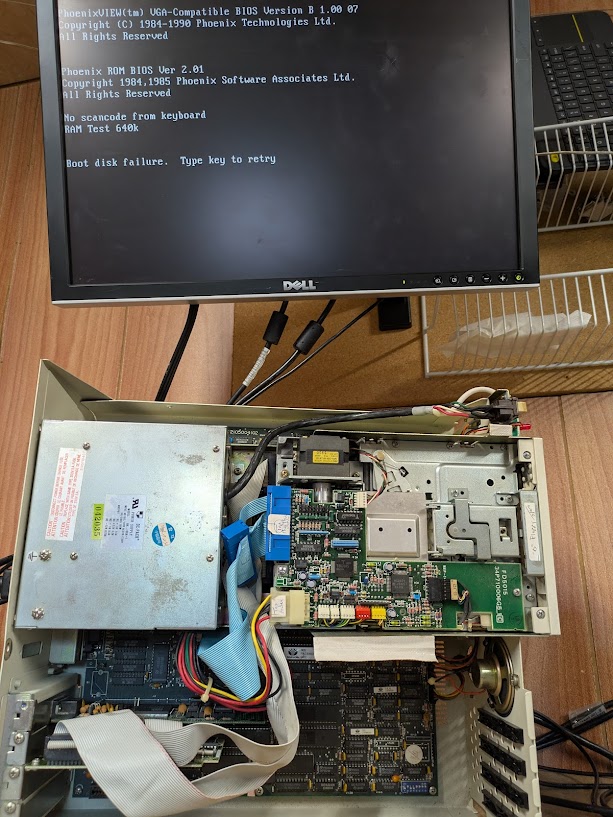
But before I go – witness the beauty of one fully-working Leading Edge Model D!! Since I lack an XT-compatible keyboard, I cannot control it, but it does boot and stays responsive!
![]()